
- /
- Overview
- /
- List of Figures
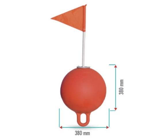
Figure 1: Illustration of flagpole with a buoy.
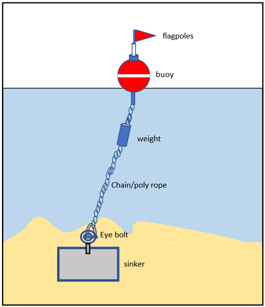
Figure 2: Example of buoy with a sinker.
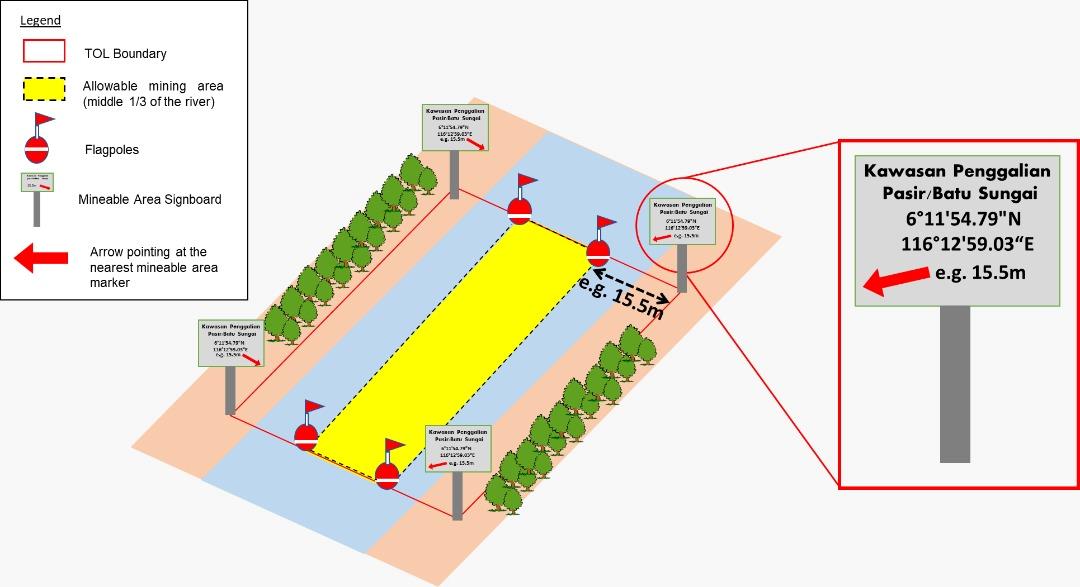
Figure 3: Illustration showing the mineable area marking.
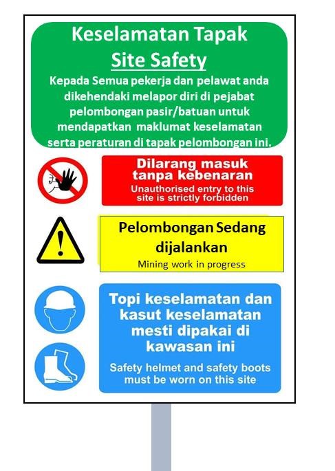
Figure 4: Example of a warning signboard.
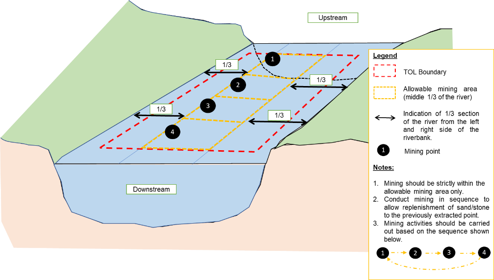
Figure 5: Illustration of mining sequence within the middle third of the river.
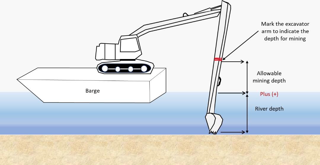
Figure 6: Illustration of measuring and marking the excavator arm.
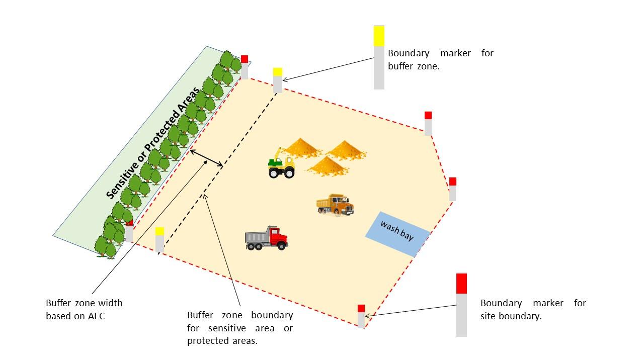
Figure 7: Illustration showing site boundary marking and buffer for sensitive or protected areas.
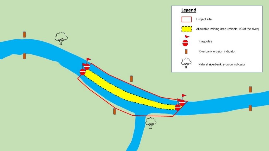
Figure 8: Illustration of riverbank indicator.
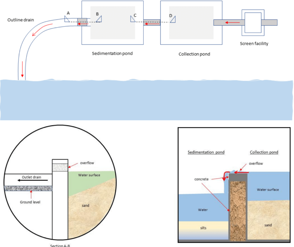
Figure 9: Plan view of sediment control facilities with cross-sections.
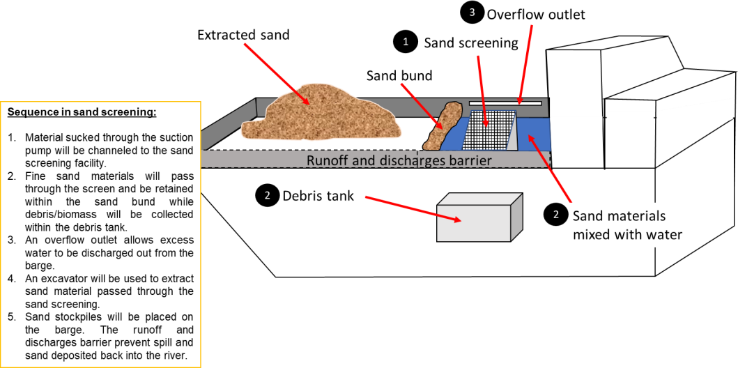
Figure 10: Example of liquid waste control structures on a barge and its function.
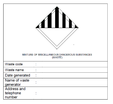
Figure 11: Example Of Label For Scheduled Wastes Container.
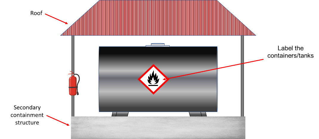
Figure 12: Illustration of an oil materials storage area.
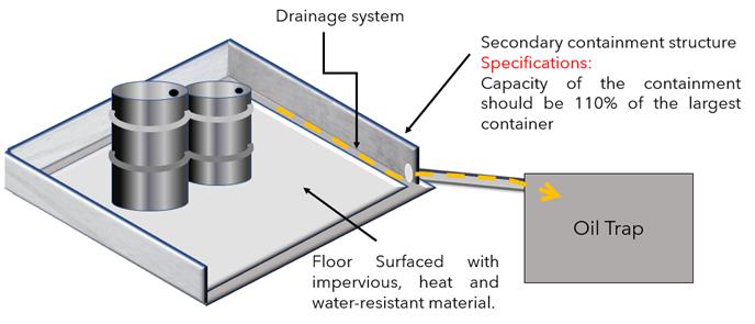
Figure 13: Illustration of a secondary containment structure and its specifications.
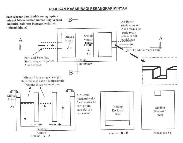
Figure 14: Typical design of oil trap.
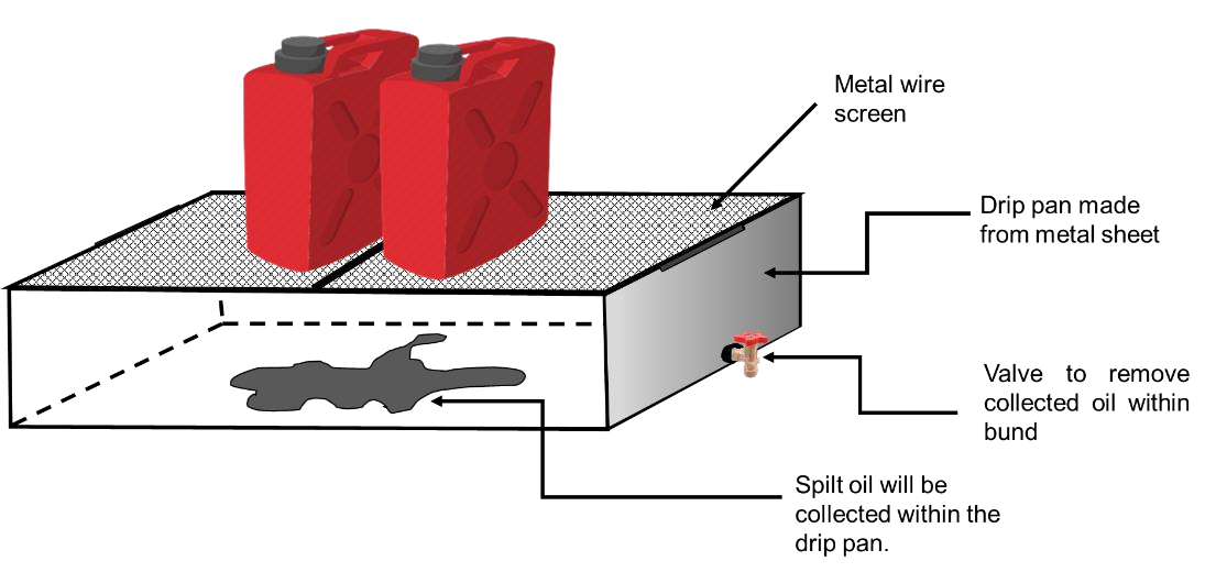
Figure 15: Example of design and function of a drip pan.
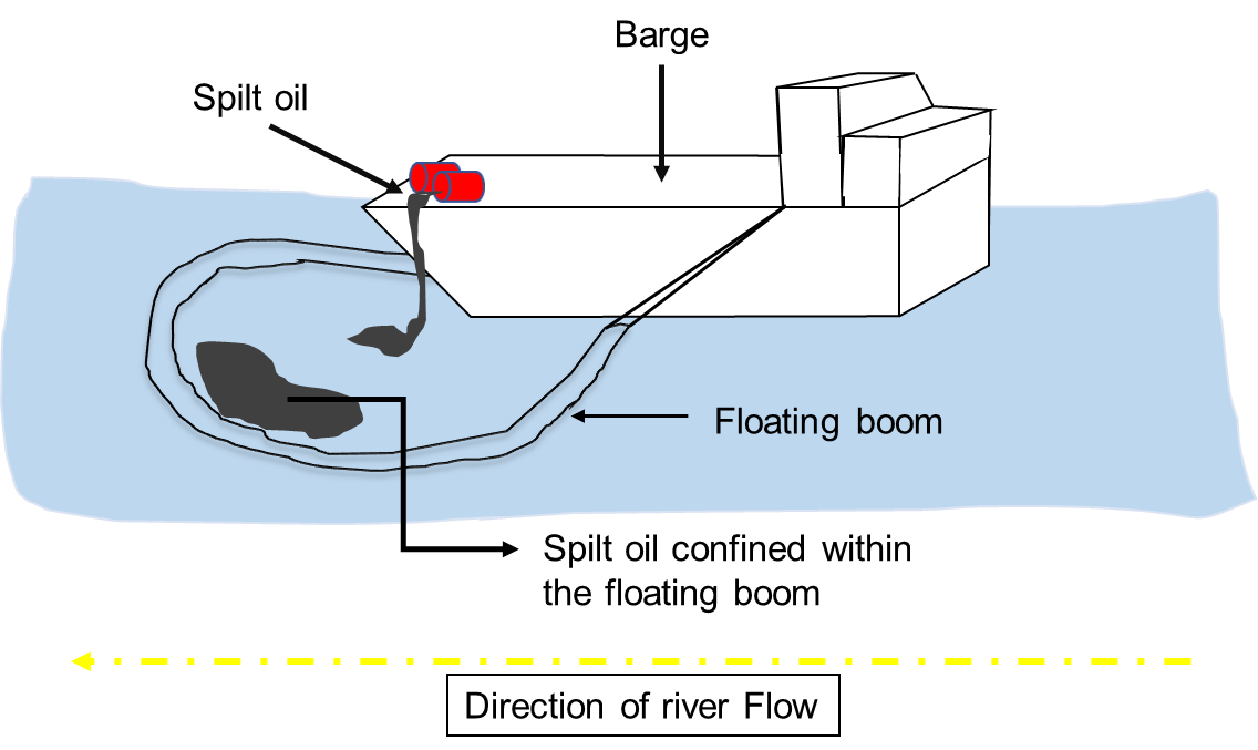
Figure 16: Example of oil spilt in river confined with a floating boom.
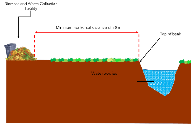
Figure 17: Measurement of 30 meter distance
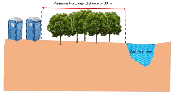
Figure 18: Illustration showing measurement of horizontal distance between toilet facilities and watercourses.
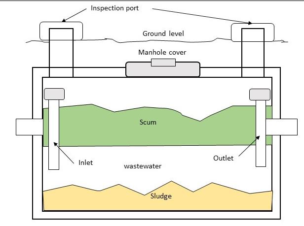
Figure 19: Illustration of a septic tank.