- /
- Site Preparation
- /
- Hydraulic (Pontoon)
- /
- Site Preparation: Hydraulic – 1.0 River Stone & Sand Mining

Uncontrolled mining of river stone and sand activities results in channel erosion of the riverbank at the extraction area causing changes in river morphology at the upstream and downstream as well as sedimentation towards the downstream river stretch.
River stone and sand mining activities within the approved allowable mining area.
1.1.1 Obtain certification from the sabah lands and surveys department on the boundary survey plan and submit to EPD together with TOL approval letter before the commencement of the mining activity.
1.2.1 Appoint a licensed surveyor to identify the location of markers for the mineable area based on the approved figure in the AEC.
1.2.2 Install easily visible markers to demarcate the mineable area before commencing mining activities examples of mineable area markers that can be used are:
(A) Flagpole with buoy
i) The illustrations of flagpole with buoy and sinker are shown in figures 1 and 2 these markers are usually used in deep rivers.
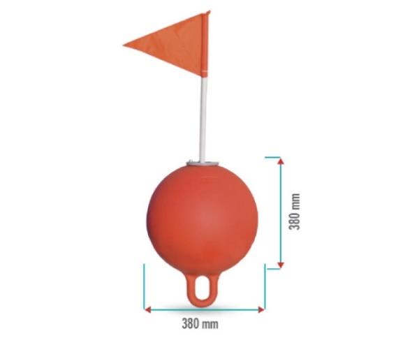
Figure 1: Illustration of flagpole with a buoy.
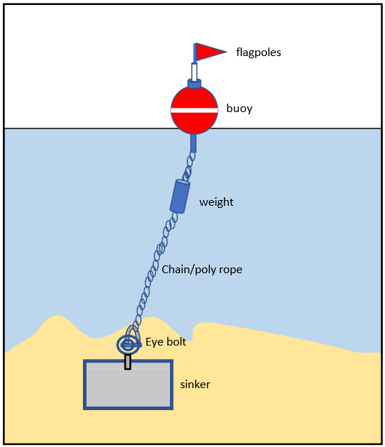
Figure 2: Example of buoy with a sinker.
ii) Connect the buoy with the sinker by using a chain or rope with an extra 2 m added to the total length in order to keep the buoy at a specified radius on the surface.
iii) As an alternative method empty gallons that are free from chemicals/oil residue can be used to replace the buoys.
(B) Flagpole
i) Erect iron poles with flag in the river at depths that can withstand river currents these markers are usually used in shallow waters.
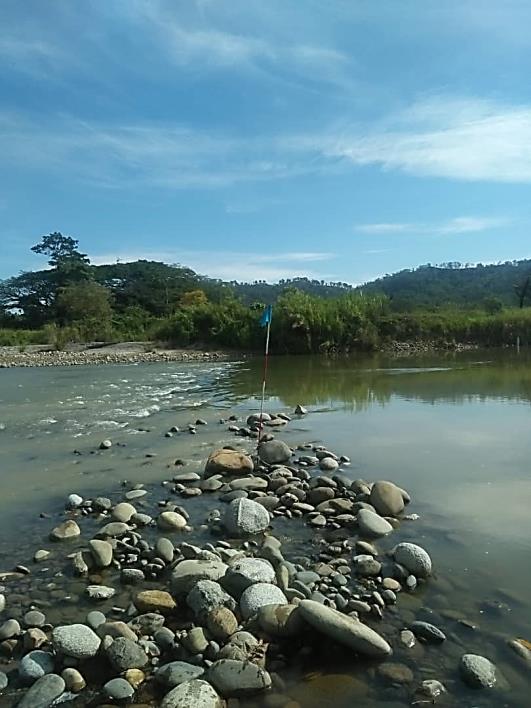
Plate 1: Flagpole used to mark the mineable area.
1.2.3 Consider river conditions when selecting marking tools used to mark the mineable area.
1.2.4 Use bright colours for the mineable area markers and make the markers easily visible for example use red colour.
1.2.5 Erect suitablysized signboards that are easily visible at the riverside to mark the starting (upstream) and ending (downstream) point of the mineable area or erect signboards at the location shown in the figure in the AEC the recommended size for signboards are 0.5 m x 1.0 m.
1.2.6 Signboards should state the following information:
1.2.7 Install a warning signboard next to the mineable area signboard or erect a warning signboard at the location shown in the figure of the AEC to warn the public of mining activities.
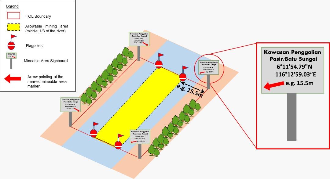
Figure 3: Illustration showing the mineable area marking.
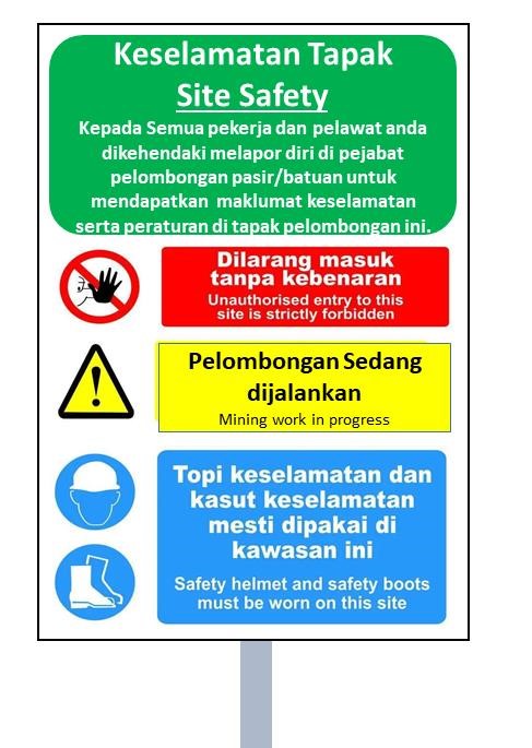
Figure 4: Example of a warning signboard
1.2.8 Conduct patrolling activities to check the condition of the signboards and mineable area markers.
1.2.9 Replace or conduct necessary maintenance if the marking has been removed or damaged during floods.
1.2.10 Prohibit any river reclamation activities.
1.3.1 Refer to the EIA/AEC for the location of the access point/route to the mining area.
1.3.2 Conduct minimal clearing for the preparation of access point/route. Access route width is based on the width of equipment use for mining.
1.3.3 Layer the access point/route with aggregates to minimise erosion from runoff.
1.4.1 Conduct river stone and sand mining activity based on the approved methods specified in EIA.
1.4.2 Conduct river stone and sand mining within the mineable zone only (middle third of the river within the approved TOL boundary or based on the environmental consultant assessment during the EIA stage along with the DID requirement) based on the AEC.
1.4.3 Stop river sand or stone mining operations during or after heavy rains to avoid increasing suspended solids and turbidity levels in the river.
1.4.4 Conduct mining in sequence (refer to Figure 5) to allow for replenishment of river sand/stone at the previously extracted point and avoid an abrupt change in gradient.
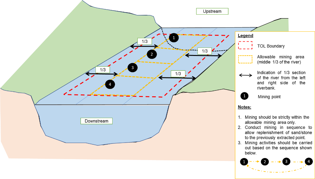
Figure 5: Illustration of mining sequence within the middle third of the river.
1.4.5 Prohibit excessive excavation at the allowable mining area to minimise the change in river. Refer to the following section.
1.4.5.2 Hydraulic Method (Suction Pump on Pontoon).
This method involves the use of specially built equipment to dredge sand i.e., suction pump. Generally, a suction pump is sited on a pontoon. The suction pump pipe channels sand to the processing site, which is either located on land or on a barge (the pontoon is attached to a barge).
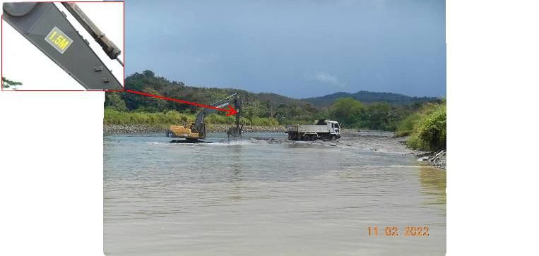
i) Equip the suction pump cable with a clamp to limit the suction pipe at the allowable mining depth based on DID requirement. Refer to Plate 4 for the example of the suction pump cable with clamp.

Plate 4: Example of suction pump cable with clamp.
1.4.5.3 Check the mining depth from time to time to avoid excessive excavation. It is recommended that an in-house surveyor is appointed to determine the mining depth based on the current river invert level, baseline river survey plan and the DID’s allowable mining depth.
1.4.5.4 Closely monitor changes in the bed and bank of the river as described in Appendix 1. When the allowable longitudinal profile and cross-sections of river have been reached, the mining activity shall be stopped. Any further excavation will cause unacceptable riverbank erosion and lowering of the river depth.